Table of Contents
The following article is an original source work from the late 1980s describing the discovery of variable frequency drive induced electrical motor bearing damage by the gentleman who invented SGS™ shaft grounding systems.
Background
The inventor of SGS™ shaft grounding systems, Hugh Boyanton, is often credited with having originally isolated the problem of electrical bearing damage and its cause. The following is an abbreviated version of his original work completed during the mid to late 1980s that resulted in finally determining the cause of electrical bearing damage related to variable frequency drives (VFD). It would be many years after this article was published when others, such as drive manufacturers, maintenance professionals and system owners began to understand that there was an inherent and unexpected problem with VFD motors.
This original work was completed at Willamette Industries, a pulp & paper mill located at the time in Albany, Oregon. Having been developed in a paper mill, SGS™ was forced from the beginning to be an extremely robust and effective device that had to withstand the harshest of 24/7 industrial environments. Unscheduled downtime was not an option. It’s this product DNA that continues to allow SGS™ to be the most robust and longest lasting shaft grounding device on the market.
Abstract
The frosted, fluted or corrugated pattern often found on the surface of the inner or outer race of an anti-friction bearing is often the result of electrical damage. This type of damage reduces the life of bearings that should last from six to ten years to as little as four months. It is estimated that hundreds of millions of dollars are lost to this class of bearing damage. This type of bearing damage is widespread in the HVAC industries and manufacturing industries such as mining, pulp & paper, metals, semiconductors, commodity loading, plastics extrusion, and food processing.
The search leading to the discovery of a major class of bearing damage will be discussed in this paper, along with several factors that mask the underlying causes of this problem.
Bearing Frosting and Fluting Problems Have Long Been Recognized
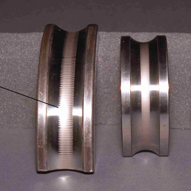
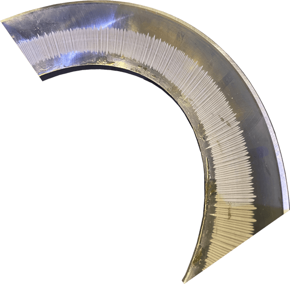
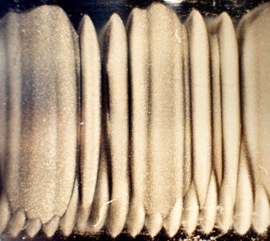
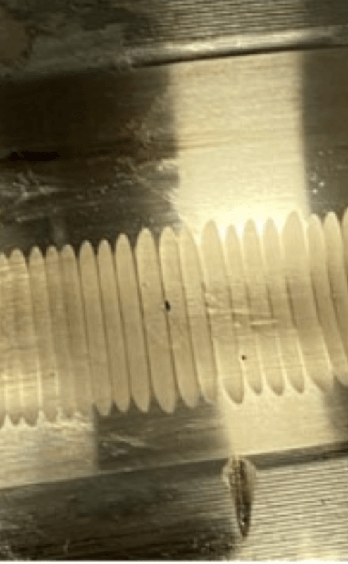
Examples of bearing fluting are shown in figures 1 through 5. Note that the flutes have a very regular “machined” appearance. In the case of the roller bearing race shown, the fluting is very narrow and closely spaced. This fluting pattern is often seen in association with continuous manufacturing processes that are operated at one speed for several hours at a time. Where running speeds vary widely with no predominate speed, “frosting” may be seen instead of fluting.
A literature review indicated no previous solution to this fluting problem. A number of theories were presented, but the research was not effective in isolating a clear cause, or the cost, to industry.
We Can Now Better Define a New Class of Electrical Bearing Damage
A separate class of bearing failure due to electrical currents passing through bearings is characterized by fluting and in special cases by frosting of bearing races. The investigation leading to this discovery will be presented here.
The class of bearing failure is associated with “shaft currents” which flow because of shaft-to-frame electrical potentials. A major source of the “shaft currents” in this class of bearing failure is the potential induced between the rotating element and the static element in variable speed electric motors. This potential is associated with the use of solid-state gating devices used to generate DC current for DC motors or AC variable frequency (VFD) power for AC motors.
For purposes of this discussion, this class of bearing failure will be called “ED” damage or electrical discharge bearing damage.
Obstacles to the Discovery of a New Class of Bearing Failure
Why wasn’t this cause of electrical damage to bearings and its growing importance as a major cause of failure seen earlier? There have been several obstacles to understanding the cause of electrical damage to bearings and the generally widespread distribution of the problem. Over time these have been removed. This has permitted a breakthrough. Some of the underlying factors leading to this breakthrough are:
- In general, consumers have raised their expectations. In the past, industry has accepted short bearing life as unavoidable. Maintenance systems were established and budgeted to repair the ongoing damage. This reduced the motivation to understand the cause of electrical bearing damage such as fluting. Now many consumers and maintenance groups are challenging the assumption that bearing life should be other than the design life, which is often 100,000 hours or more.
- Often, electrical current can migrate and damage bearings or contacting surfaces of another piece of connected equipment, such as a tachometer, gear box, fan, or pump. Electrical bearing damage such as fluting or frosting can occur in any of the equipment connected to variable speed electric motors, or to another source of electrical potential. Any available parallel electrical path is subject to this class of bearing damage. This effect conceals the common underlying cause.
- A sequence of failures such as: tachometer failing first, followed by a motor bearing failure, followed finally by a gearbox failure, is unlikely to be seen by repair and maintenance groups who typically make the repairs. They will not connect these events as a continuation of a common problem. This effect is so important that end users with serious electrical bearing damage will most often strongly assert that they have no electrical bearing damage problems until they are made aware of where to look and how to isolate the source of the problem.
- Preventative maintenance has improved steadily until several other major classes of bearing failure have been understood and controlled. Failures such as those due to lubrication and misalignment are now greatly reduced due to improvements in equipment design, installation, and maintenance practices. This has permitted the damage due to electrical currents to now emerge as a major cause of bearing failure where variable speed electrical equipment is used.
- Predictive maintenance has only recently become a widespread practice. Only in the last five to six years has predictive maintenance become a major maintenance activity. With the advent of vibration analysis, the problems have been found before catastrophic failures occurred, which usually destroyed the evidence, preventing effective failure analysis.
- Failure analysis to determine root cause is now demanded by an increasing number of equipment builders and end users. In the past, this was commonly not carried out. This is still a problem where overhaul and repair is carried out by repair facilities that do not routinely perform failure analysis. Failure analysis is often not done by independent contractors or repair shops. These facilities are often forced to compete on the basis of price and short turn around times which do not include failure analysis or detailed information as to how the equipment was used.
- The rate of electrical damage to bearings can vary. Occasionally, the rate of damage is very rapid, resulting in bearing loss within four to six months. More often, damage takes from one to two years to reach the point where the bearings should be changed. This creates a situation in which the new equipment warranty has expired, effectively preventing the original equipment manufacturer from having adequate information regarding the life of original bearings.
- Other classes of electrical damage, such as eddy currents, have, at times, been confused with this newly redefined class of electrically caused bearing damage. When bearing fluting or other evidence of electrical damage was clear, the cause was frequently believed to be due to a local condition relating to power supply, grounding, or to a specific vendor or product. This has distracted many from the general and widespread incidence of this class of bearing damage.
- Equipment failures after running periods of a year are subject to interpretation as a failure due to misuse or improper maintenance. Good maintenance organizations are action oriented and tend to accept failures as somehow preventable if they only do their job better. They do not often look first for another class predisposing cause.
- In general, manufactures are doing more with less. Equipment is more efficient and cost competitive. The growth in the application of solid-state electric motor drives and controls has eliminated the need for expensive and difficult to maintain equipment such as mechanical variable speed power transmission systems or mechanical modulation of process flows using control valves. The result is simpler, economical systems that are very price competitive. It has also dramatically increased the sensitivity of equipment to electrically caused bearing damage. This is further aggravated by the elimination of connected systems such as gear boxes or tachometers that have bearings that serve as sacrificial elements.
A Serious Bearing Failure Problem Prompted a Closer Look Into Electrical Bearing Damage
A serious DC motor bearing failure in a paper manufacturing operation prompted us to begin research into this subject. The loss of motor bearings in this continuous operation resulted in large, unexpected maintenance and downtime costs. Over a three-year period, a large number of bearings (over 40) in a population of 26 large DC motors and a small number of AC variable frequency drives used on one paper machine system were damaged and subsequently replaced. Some of the bearings were replaced more than once. The cost of the repairs was well over $100,000 (adj. for inflation, $300,000). The cost of lost production during downtime was over $41,000 per hour.
After working through a number of suggestions and applying several suggested modifications, it became apparent that the combined efforts of the customer and the vendor were not resolving or eliminating the persistent bearing damage.
At this point, an independent project was undertaken without vendor support to investigate the cause of the bearing failures and to develop a solution to the problem.
The Area of Research Was Centered Around Motors Running DC and AC Electronic Drives
In this situation, it was observed that the electrical damage to bearings seemed to be primarily associated with the variable speed electronic drives. Therefore, the research was centered around motors powered by DC and AC electronic (solid-state) drives.
It was determined that an electrical potential existed between the rotating element and the static (fixed) element in DC and AC variable speed motors.
It was recognized that there are other causes of electrical damage to bearings, such as discharges, welding, broken rotor bars, and magnetized shafts (eddy currents). These are not a part of our topic.
Work to Rule Out Alternative Explanations Presented as the Cause of This Electrical Bearing Damage
The following mechanisms were suggested as possible causes of the bearing damage within this system of 26 DC motors. Each was tested to determine if it constituted significantly to the ED class of bearing damage.
1) Multiple drives on one large transformer can cause electrical bearing damage.
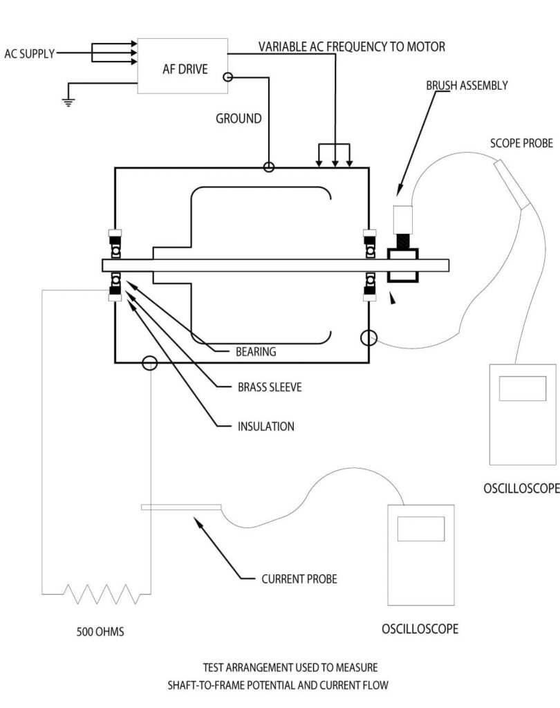
a) We took a variable frequency drive and AC motor, and a DC drive and DC motor. We then fitted them with a pickup that would allow us to measure the potential from the shaft to the frame of the motor. This was done using an insulated brush holder with a carbon brush riding on a brass sleeve shrunk onto the motor shaft. (See Figure 6 showing a sketch of the setup). We used a Fluke Model 97 battery powered digital oscilloscope to measure the potential. This eliminated any influence from the local power supply upon the measuring equipment.
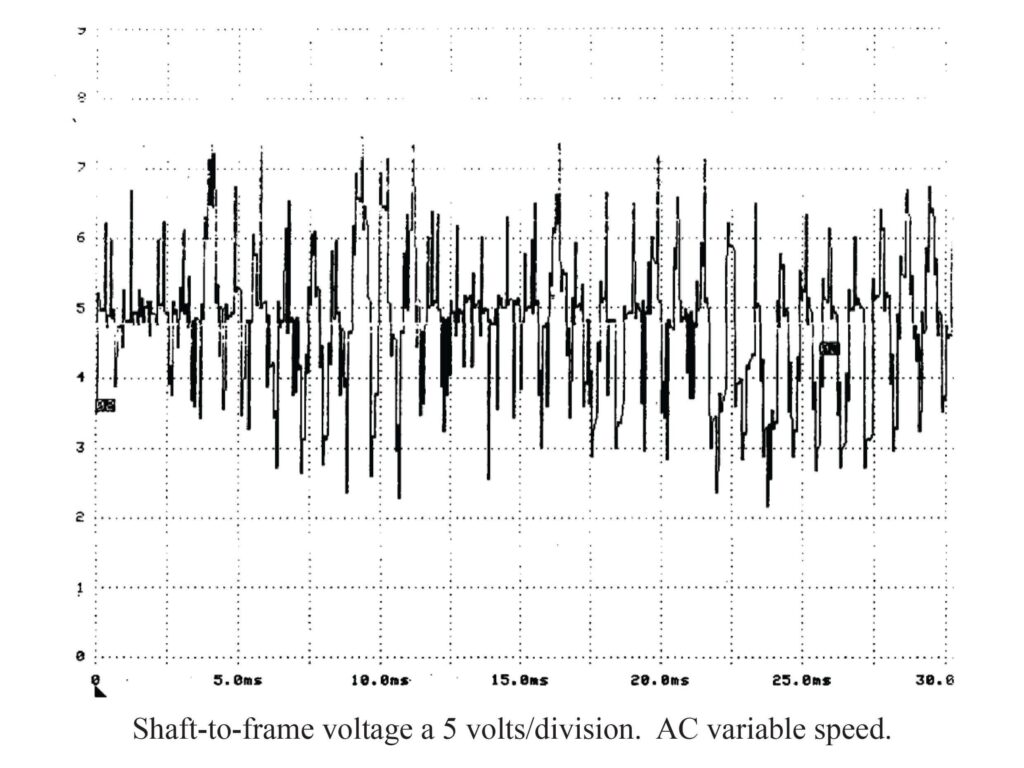
b) The drives were first connected to a transformer that had twenty DC drives on it, driving the dry end of a paper machine. We measured the shaft potential and we observed spikes as high as 70 volts on the DC motors and 30 volts on the AC motors. The occurrences were sporadic as well, and the polarity of the voltage spikes was variable. (See Figures 7 and 8 showing the oscilloscope traces.)
c) We next powered each drive separately from a power source that had no electronic drives involved. We observed no substantial differences in the display on the oscilloscope.
d) We moved the drives to a separate facility that had an entirely different AC power source. Again, we observed the same voltage readings as before.
It has been suggested that a number of electronic drives on one transformer would cause harmonics to be impressed back onto the AC line. It had been suggested that these harmonics were causing capacitive coupling across the motor bearing, causing bearing damage.
2) An improper building grounding system can cause electrical bearing damage.
a) Using the same two drives, we connected the ground system as per the drive manufacturer’s recommendations. This provided added assurance that we had a good ground system. We measured the shaft potentials. There were no differences.
b) We also tested shaft-to-frame voltage at the alternate facility. We observed no differences.
Another suggestion was that we might have had a high resistance ground connection, or even an open ground system. Also, there was a concern that this could be due to circulating currents within the system.
3) Harmonics on the AC power system.
- We ran the drives on three separate AC power systems to evaluate the impact of the plant AC power system. These systems were as follows:
- 1. The industrial plant where we initially encountered the problem.
- 2. A separate facility with no equipment running except for lights.
- 3. A three phase 480 volt AC diesel generator with nothing else on it.
- No measurable difference was noted in shaft potentials.
- We ran the drives on three separate AC power systems to evaluate the impact of the plant AC power system. These systems were as follows:
The Search for Root Cause of Electrical Discharge Bearing Damage
It was reasonable to us that these suggested causes, or theories, did not seem to be consistent with what we were seeing. We thought that if we could isolate the source of the shaft-to-frame potential, and time it, we could trace it back to its sources. This was approached in the following manner:
1. The DC and AC motor bearings were insulated on both end by machining out the end bells of the motors and pressing in a phenolic insulating material.
2. An insulated conductor was attached to the outer race of each bearing and ran to the outside of the motors. This allowed us to operate each motor with either one or both bearings insulated. It also allowed the motors to be operated with insulated bearings.
3. First, we tested the DC motor with only one bearing insulated. We saw a slight increase in shaft voltages with the same sporadic spikes, similar to those shown in Figure 7.
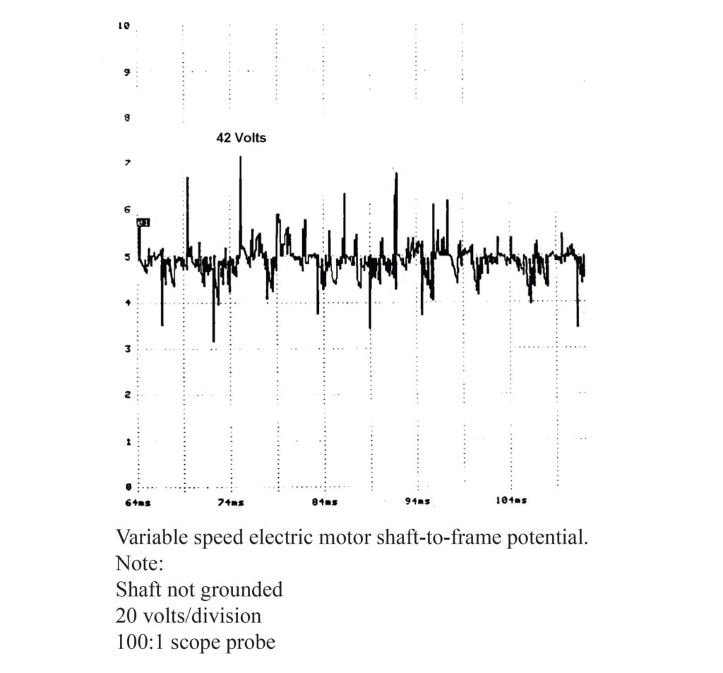
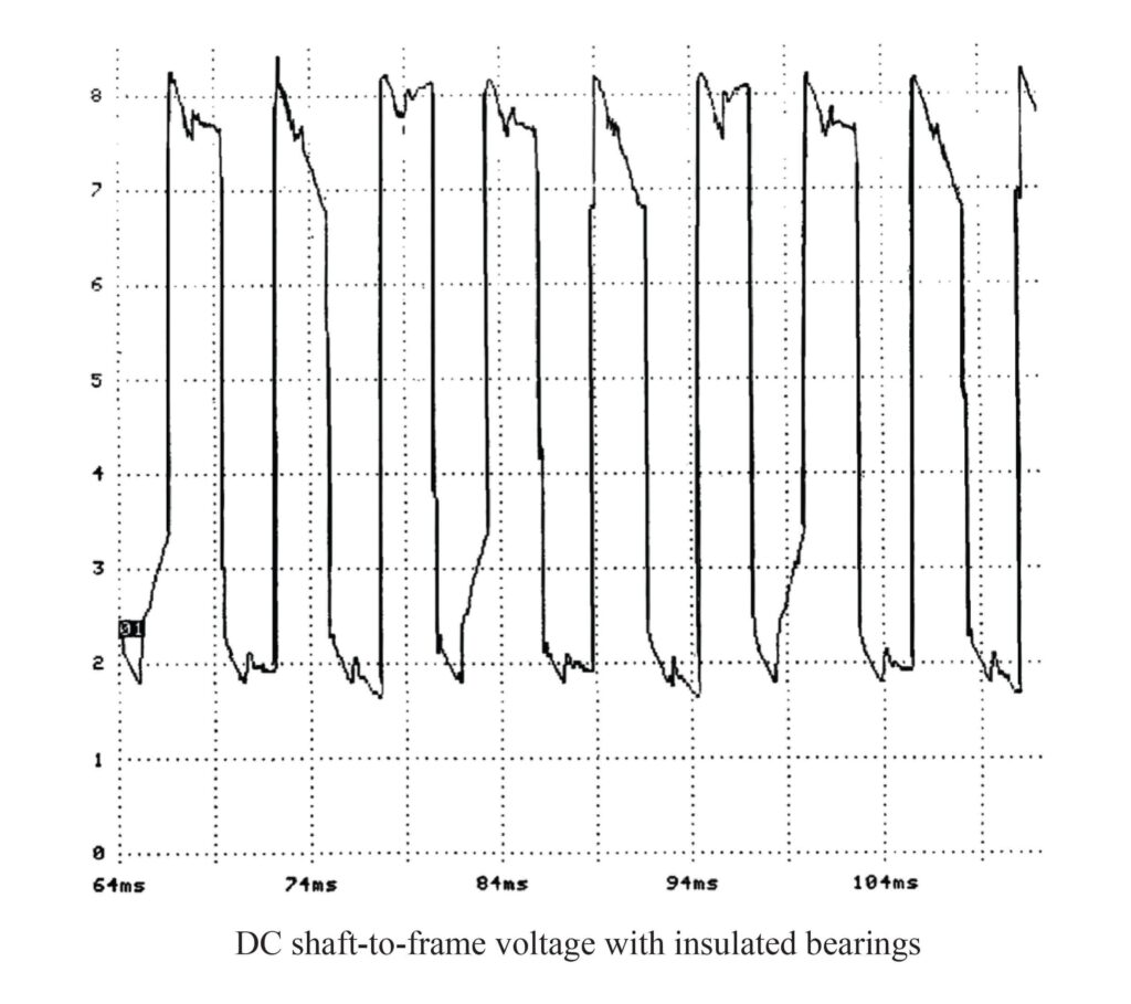
- 4. We then insulated both bearings in the DC motor and observed something that had not been observed up to this point. A voltage level as high as 270 volts, and polarity changing 360 times per second (see Figure 9) was observed.
5. Using a recording oscilloscope, we recorded the output of the drive going to the DC motor on one channel, and the shaft-to-frame potential on another channel. It was evident that the source of the shaft-to-frame potential was synchronized with the firing of the solid-state drive silicon controlled rectifiers (SCRs). (See Figure 10).
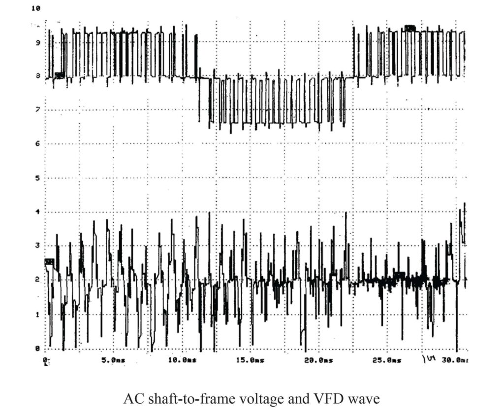
- 6. Next, we repeated these tests using the AC variable frequency drive and motor. The voltages were not as high, but the frequency of the voltage spikes was found to be much higher (see Figure 11). It was apparent that, each time the drive system transistor would turn on or off, the effect could be seen as a shift in the shaft-to-frame potential.

Establishing When Current Would Flow Through the Bearing
At this point, we believed that we had correctly identified and isolated the source of the shaft-to-frame voltage potential. We also saw that, if this voltage was great enough, then it would cause current to flow, causing the electrical discharge (ED) type of bearing damage. The following information was determined by testing:
- 1. We tested both units and found that insulating just one end of the motor would actually cause the rate of ED bearing damage to happen more quickly in the uninsulated bearing.
- 2. We also determined that if there was a discharge path available in the motor or connected equipment, and the potential on the shaft rose beyond a certain level, then the dielectric strength of the lubricant would be overcome, and current would flow. (See Figure 12.)

pathways from shaft to frame through the bearings.
- 3. In trying to identify the “break-over” voltage of the lubricant, we set up a test using a Variac power supply (a variable AC power supply). We took a mild steel shaft and installed two bearings, one on each end of the shaft. The shaft was driven with an 1800rpm motor through an insulated coupling.
- 4. We also installed two insulated electrical brush holders, one at each end of the shaft. On one of the brush holders, we connected one side of the variable AC power source and connected the other side to the two bearing housings.
- 5. The Fluke oscilloscope was connected to the other brush holder, and the ground was connected to the two bearing housings (See Figure 13.)
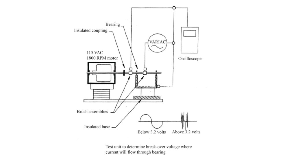
- 6. When the voltage on the shaft was below 3.2 volts, we saw a 60hz sinusoidal wave form. When the potential on the shaft exceeded 3.2 volts, we saw an erratic looking signal on the oscilloscope, suggesting current had begun to flow. When the voltage was lowered below 3.2 volts, the 60hz sinusoidal wave form would return.
Our conclusion is that the break-over voltage is dependent upon the thickness of the film lubricant and on other motor running conditions such as temperature.
Shaft-to-frame Voltages in Standard AC Motors Running Across the Line
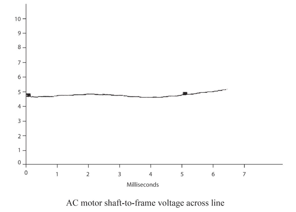
The shaft-to-frame potential on a conventional (non-adjustable frequency) AC motor was tested. This data was taken with the motor running “across the line” (not running on a variable frequency drive). Voltage levels ranging from 0.1 volt to 2 volts were measured. The voltage seemed to vary this amount from motor to motor. As long as there was not any current flow, there was no damage to the bearings (See Figure 14.)
Determination of the Amount of Current During a Voltage Spike
The amount of current flowing during the break-over period was difficult to measure. We set up a test that would enable us to measure the current during a spike. The modified AC motor with insulated bearings and lead out conductors were used to investigate this. A 500 ohm resistor was placed in series with the conductor from the outer race of the bearing and connected to the frame of the motor. Using the current probe on the Fluke oscilloscope, we could see a current flow of .5 amps to .75 amp during the period of the spike. One of the drive manufacturers, who reproduced the test, recorded current spikes as high as 2.02 amps.
Similarity of Electric Discharge (ED) Bearing Damage to Electric Discharge Machinging (EDM)
What is really taking place when the bearing is being damaged by current flow?
Further investigation found a similar process that has been used since 1962 called electric discharge machining (EDM). Electric discharge machining has been used in the mold making industry where very hard metals are used, or inside corners must be made. The EDM process removes metal by passing a periodic current through an oil film to remove small amounts of metal. The EDM process uses close tolerances between the work and an electrode as well as voltage levels similar to those seen in the shaft-to-frame voltage measurements taken during our research. Additionally, the shaft voltage is generated using solid state technology.
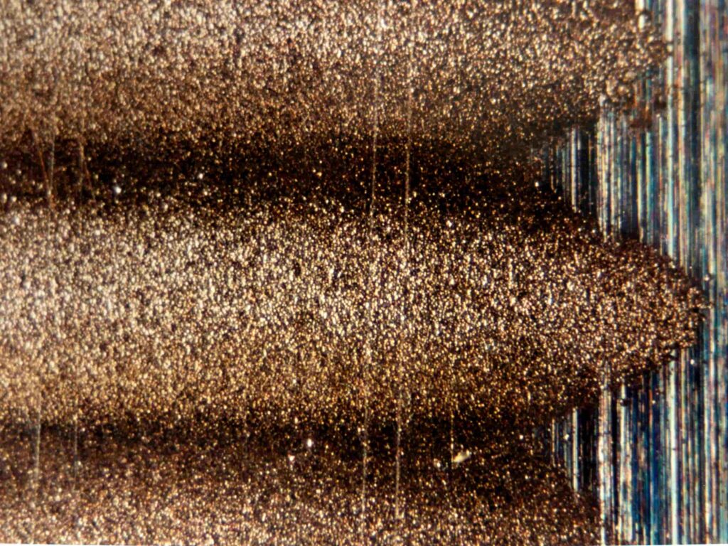
In the operation of a bearing, rolling elements are riding on a layer of lubricant, keeping the inner and outer races separated from each other by 150 to 250 millionths of an inch. When the potential on the shaft reaches a critical point, the dielectric strength of the lubricant is overcome and current flows. This creates microscopic pits burned in the rolling elements and the races of the bearing.
These discharges across the bearing occur millions of times per day, gradually breaking down the surface of the races and rolling elements. The first appearance of damage that can be seen by the human eye looks like frosting or very fine sandblasting. The material that is removed from the races or the rolling elements is either redeposited on itself, or is entrained in the lubricant, causing further mechanical damage.
Development of the Fluted or Corrugated Pattern in ED Bearing Damage
The fluted pattern appears to be the result of several factors:
- The fluted pattern is caused by the firing rate of the electronic gating device such as SCRs, transistors, IGBTs, or GTOs.
- The size of the bearing (ball pass frequency).
- The RPM of the motor. When the motor runs at one speed for a long period, the discharges across the bearing are periodic and the ball pass frequency is the same. The resultant discharge occurs at the same points on the race each time, machining out microscopic amounts of metal.
We see bearings that have come out of motors that have run at widely varying speeds where there is no fluted patterns. Instead, the bearing races are machined smooth around the entire inner/outer race of the bearing. This type of defect often provides no advanced warning, such as the noise generated by the fluted pattern. This can lead to catastrophic failure with little warning. This problem has been attributed to lubricant failures.
The Magnitude of Electrical Discharge Bearing Damage
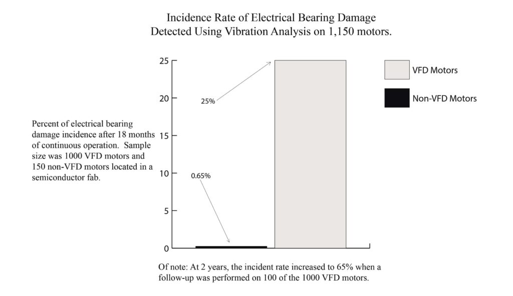
After having identified that VFDs were responsible for electrical bearing damage, we carried out a large study in a semiconductor plant using vibration analysis on 1,150 AC motors. One thousand of these motors were powered by variable frequency drives (VFDs). One hundred and fifty motors were non-variable speed driven (across the line). These motors were all used in similar clean room applications (See Figure 15).
The data showed that 25% of the VFD motors in operation for less than 18 months had bearing damage caused by electrical discharge (ED). The data also showed that 65% of VFD motors that had been in operation for greater than 18 months, with an average age of two years, had ED damaged bearings.
The 150 motors that were running across the line were found to have an incidence of bearing damage of less than one percent (See Figure 15). This problem is not limited to the clean room industry or to AC motors. We have seen DC motor bearing damage due to ED in every industry examined to date. A consultant in California said 90% of the bearing damage he has seen in DC motors has been caused by current flow through the bearings.
Since our initial investigatory work at the paper mill, we have visited over 400 industrial sites across the United States and overseas and have found electrical discharge damage to bearings. We are forced to conclude that where electronic drives are being used, electronic discharge damage is in process. The location and rate of damage will vary. The damage may be found in tachometers, motors, gearboxes, or other connected equipment. The sensitivity of the user to downtime and repair costs will vary, but the damage will occur. We have found no motor or drive combination to date that is free of the problem.
The way to prevent ED is to provide a safe, very low impedance path that will allow the potential to be reduced so that the bearing will not be damaged. This is done by electrically connecting the rotating shaft to the frame. This puts the shaft and the frame at the same electrical potential.
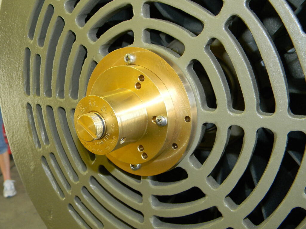
A Long-term Fix: SGS™ Shaft Grounding
A significant problem that continues to challenge the overall shaft grounding market to this day are devices that cannot maintain a path of least resistance for current to flow for the long-term.
Industrial environments require robustly built devices to function properly in challenging situations. SGS™ shaft grounding systems continue to be the most robustly built and reliable shaft grounding solution available on the world market. Having been in the field for four decades, SGS™ systems have solved the “environmental” factor that quickly damages and prevents the other devices from functioning properly for the long-term.
SGS™ continues to demonstrate better than any other product that a high-tech problem can be resolved through a simple, robust, mechanical solution.